High Availability Changes in Exchange Server 2010? DAG part 2
Introduction
In the first part of this multi-part article uncovering Exchange 2010 Database Availability Groups (DAGs); we had a look at what Exchange 2007 and earlier versions provided when it comes to native high availability functionality for Mailbox servers.
In this part of this multi-part series, I will provide the steps necessary in order to prepare two servers to be used in a two DAG member solution. Both Exchange 2010 servers are placed in the same Active Directory site in the same datacenter. Multi-site DAG deployments will be uncovered in a separate article here on MSExchange.org in a future article, since this type of deployment includes many considerations and additional details. Also, even though these servers will be configured as multi-role Exchange 2010 servers, I will not uncover redundancy configuration for the Hub Transport and Client Access server roles. Redundancy for the Client Access server role and the new RPC Client Access service has already been covered in a previous articles series of mine (can be found here). Redundancy in regards to the Hub Transport server will be uncovered in a future article.
Test Environment
The lab environment used as the basis for this multi-part article consists of one Windows 2008 R2 domain controller, one Windows Server 2008 R2 file server (will be used as witness server), and 2 domain-joined Windows 2008 R2 Enterprise edition servers on which Exchange 2010 will be installed. We use the Enterprise edition because DAG requires the Enterprise edition. This is because like CCR and SCR, DAG still utilizes part of the Windows Failover Cluster component (heartbeat, file share witness, and cluster database). The Exchange 2010 Client Access, Hub Transport and Mailbox server roles will be installed on both of the Windows Server 2008 R2 servers. Furthermore, note that the Exchange 2010 DAG functionality itself is not dependent on Exchange 2010 Enterprise edition (only Windows Server 2008 R2 Enterprise edition). This means that you can use the standard edition of Exchange 2010 (or the evaluation version) if you are going to follow along in your own lab. The standard edition just limits you to a total of 5 databases (including active and passive copies) on each Exchange 2010 server.
Each Exchange 2010 server has 2 network cards installed, one connected to the production network and another connected to an isolated heartbeat/replication network. Although it’s a general rule of thumb to use at least two NICs in each DAG member (one for MAPI access and one or more for replication, seeding and heartbeat purposes), it is worth mentioning that Microsoft supports using a single NIC for both MAPI access, replication, seeding, and heartbeats. This is good to know for the small organizations that want to utilize DAG.
As one of my intentions with this articles series is to demonstrate the support for deploying DAGs in an incremental fashion (a method explained in more detail in part 1), I will not install the Windows Failover Cluster component on any of the servers prior to creating the DAG.
Configuring Network settings
As already mentioned, two NICs have been installed in each server. Let us look at the way each NIC has been configured. To do so, open Network Connections. Here we have the NICs listed, and as you can see we have a PROD (connecting to the production network and providing MAPI connectivity) and a REPLICATION (connected to an isolated network) interface.
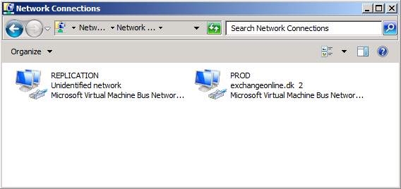
Figure 1: Network connections
Let us first open the property page of the PROD interface. Here it is typically fine to leave the default settings as is. Optionally, you can uncheck QoS Packet Scheduler and Internet Protocol Version 6 (TCP/IP v6).
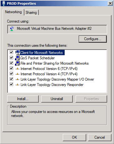
Figure 2: Properties of PROD interface
Open the property page of Internet Protocol Version 4 (TCP/IPv4). Here we have a static IP address configured as well as the other necessary settings (default gateway, subnet mask, and DNS server).

Figure 3: TCP/IP Version 4 Properties for the PROD interface
When you have configured the NIC correspondingly, close the property page by clicking OK twice.
It’s time to configure the network settings for the “REPLICATION” interface, so let us open the property page of the “REPLICATION” NIC. Uncheck “Client for Microsoft Networks” and “File and Printer Sharing for Microsoft Networks” as shown in Figure 4. In addition, you may optionally uncheck QoS Packet Scheduler” and Internet Protocol Version 6 (TCP/IPv6).

Figure 4: Properties for the REPLICATION interface
Now open property page of “Internet Protocol Version 4 (TCP/IPv4)” and enter an IP address and subnet mask on the isolated replication subnet. Since this NIC solely is used for replication, seeding and heartbeats, you should not specify any default gateway or DNS servers.
Note:
If routing on the “REPLICATION” interface for some reason is necessary between the two servers, you should use static routes instead of specifying a default gateway.
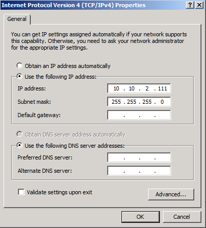
Figure 5: TCP/IP Version 4 properties for the REPLICATION interface
Now click “Advanced” and uncheck “Register this connection’s addresses in DNS” and then click “OK” twice.
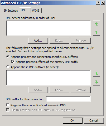
Figure 6: Advanced TCP/IP Properties for REPLICATION interface
Now that we have configured each NIC, we must make sure the “PROD” NIC is listed first on the binding order list. To bring up the binding order list, you must press the ALT key, and then select Advanced > Advanced Settings.
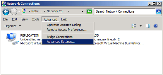
Figure 7: Selecting Advanced Settings in the Network Connection menu
If not already the case, move the PROD NIC to the top as shown in Figure 8.
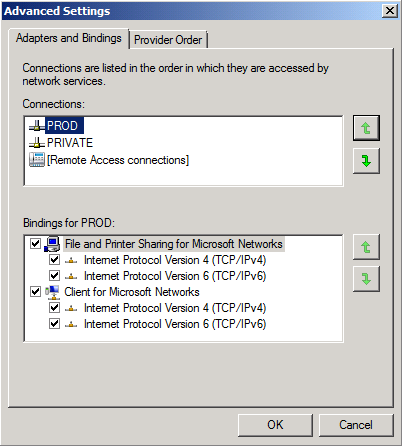
Figure 8: Binding order for the network interfaces
Click OK and close the Network Connections window.
Note:
You should of course make sure the above steps are performed on both servers.
Preparing Storage
In the specific lab used in this article series, I have created a total four virtual disks (2x30GB for logs and 2×100 for active/passive database copies) for each server. To partition the disks used for mailbox databases and logs, open the Windows 2008 Server Manager and expand Storage and then select Disk Management. Now you should right-click on each LUN and then select Online in the context menu.
Assign each LUN (disk) identically on each server as shown in Figure 10 below.
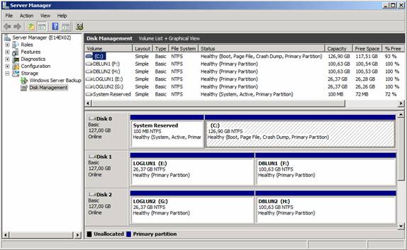
Figure 9: LUNs (disk) on each lab server
Installing Exchange 2010 Server roles
Before we can install the Exchange 2010 Server roles on the two Windows 2008 R2 servers, we must first make sure the required features and components have been installed. The following components should be installed on all Exchange 2010 server roles:
- NET-Framework
- RSAT-ADDS
- Web-Server
- Web-Basic-Auth
- Web-Windows-Auth
- Web-Metabase
- Web-Net-Ext
- Web-Lgcy-Mgmt-Console
- WAS-Process-Model
- RSAT-Web-Server
- Web-ISAPI-Ext
- Web-Digest-Auth
- Web-Dyn-Compression
- NET-HTTP-Activation
- RPC-Over-HTTP-Proxy
To install the above features, first open an elevated Windows PowerShell window and type:
Import-Module ServerManager
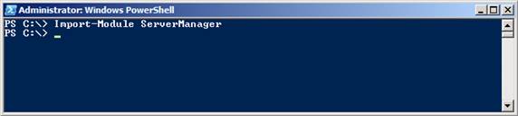
Figure 10: Importing the Server Manager module to Windows PowerShell
Then type the following command to installed the required features:
Add-WindowsFeature NET-Framework,RSAT-ADDS,Web-Server,Web-Basic-Auth,Web-Windows-Auth,Web-Metabase,Web-Net-Ext,Web-Lgcy-Mgmt-Console,WAS-Process-Model,RSAT-Web-Server,Web-ISAPI-Ext,Web-Digest-Auth,Web-Dyn-Compression,NET-HTTP-Activation,RPC-Over-HTTP-Proxy –Restart
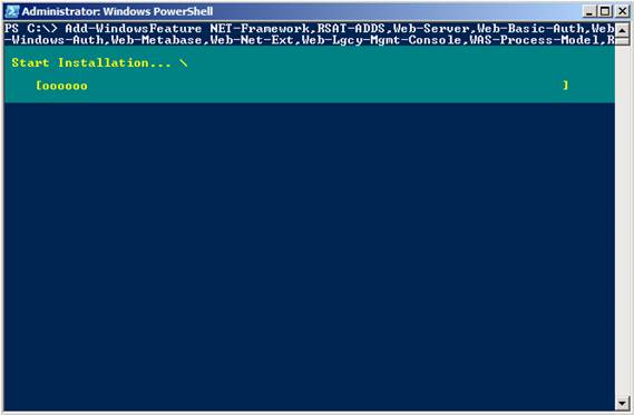
Figure 11: Installed required Windows Server 2008 R2 features
After the servers have rebooted, we must open an elevated Windows PowerShell window again, and set the service to start automatically. This can be accomplished with the following command:
Set-Service NetTcpPortSharing –StartupType Automatic
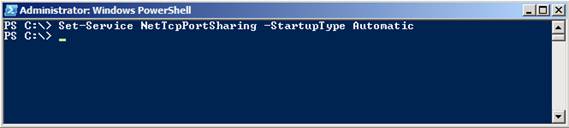
Figure 12: Setting the NetTcpPortSharing feature to start automatically
Since we are going to install both the Hub Transport and Mailbox server role on these servers, we must also install theMicrosoft Filter Pack.
We’re now ready to install the Exchange 2010 roles on the servers. So mount the Exchange 2010 media and then run Setup. This brings us to the splash screen, where we should click on Step3: Choose Exchange language option so that we can install necessary languages on the servers.
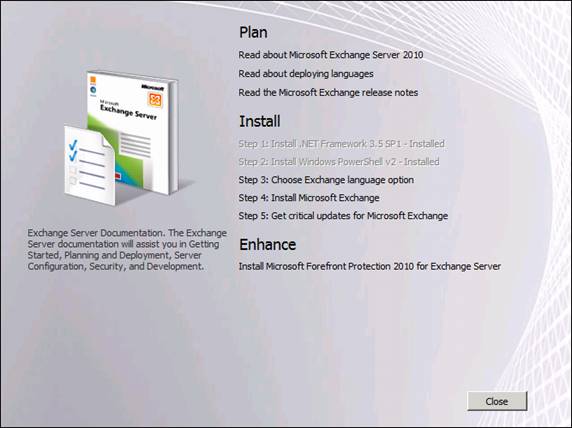
Figure 13: Selecting Step 3: Choose Exchange language option
When step 3 has been completed, we can continue with Step 4: Install Microsoft Exchange.
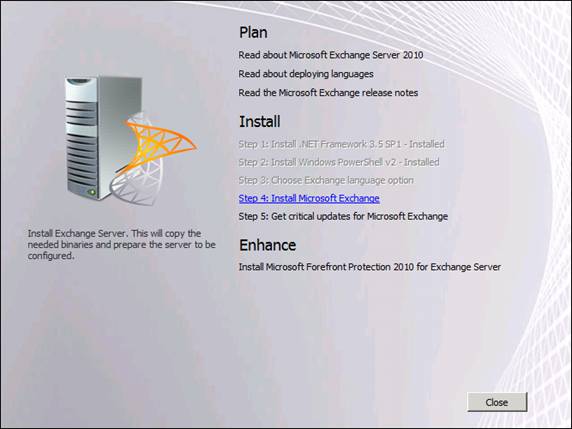
Figure 14: Selecting Step 4: Install Microsoft Exchange
On the “Introduction” page, click Next.
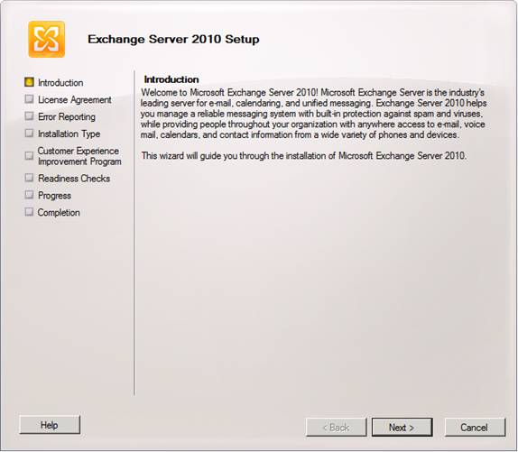
Figure 15: Introduction page5
Accept the “License Agreement” and click Next.
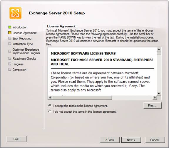
Figure 16: License Agreement page
Select whether you want to enable “Error Reporting” or not, and then click Next.
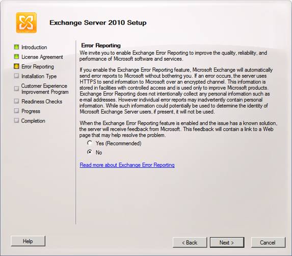
Figure 17: Error Reporting page
Since we want to install Exchange 2010 server roles included in a typical installation, select this option and click Next.
Note:
Unlike Exchange 2007, you no longer specify whether you are installing a clustered mailbox server, since the DAG functioanlity is configured when you create a DAG after setup has completed.
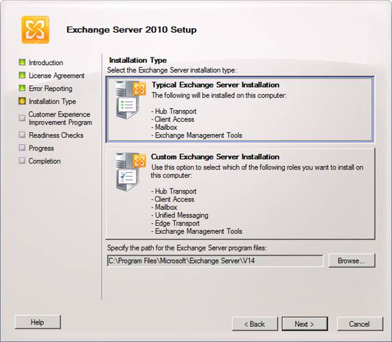
Figure 18: Installation Type page
We will now face a new page that was not included in the Exchange 2007 Setup wizard. We have the option of specifiying whether this server will be Internet-facing. In large organizations (LORGs), you typically have one Internet-facing Active Directory site and all Client Access servers in this site should usually have this option enabled. Since both servers in our little lab will be Internet-facing, we will enable the option and specify the FQDN through which Exchange client services such as Outlook Web App (OWA), Exchange activeSync (EAS), and Outlook Anywhere will be will be accessed.
When you have done so, click Next.
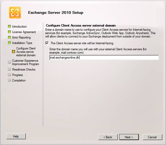
Figure 19: Configuring Client Access server external domain
Now choose whether you want to participate in the customer experience improvement program or not, then click Next.
Note:
You must also install a subject alternative names (SAN) certificate in order to get client services working properly. However, this is outside the scope of this article series.
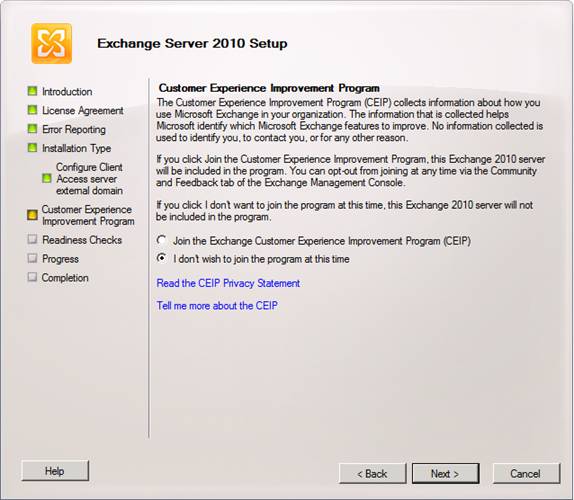
Figure 20: Customer Experience Improvement Program page
The readiness check will now begin, and hopefully you will not face any errors that will block you from proceeding. When possible, click Install.
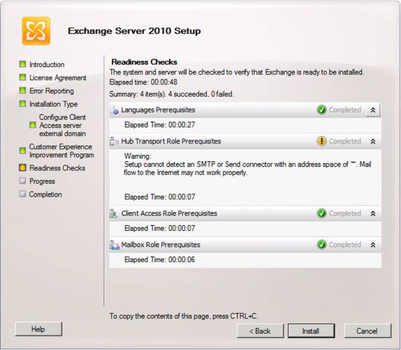
Figure 21: Readiness Check page
The Exchange server roles are now being installed.
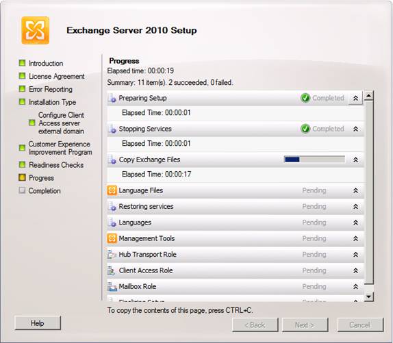
Figure 22: Installing Exchange 2010 server roles
When setup (hopefully) has completed successfully, click Finish.
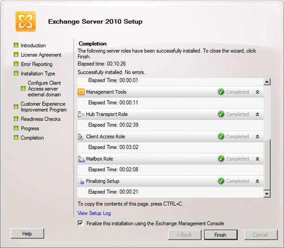
Figure 23: Exchange 2010 Server roles installed successfully
That was all I had to share with you in part 2, but you can look forward to part 3 which will be published in the near future here on MSExchange.org. In part 3, I show you how to configure a WNLB to work with a Client Access array.
—
http://blog.shiraj.com/2013/02/high-availability-changes-in-exchange-server-2010-dag-part-1/
http://blog.shiraj.com/2013/02/dag-part3/
http://blog.shiraj.com/2013/02/dag-part-4/
Categorised as: Exchange, Microsoft
Leave a Reply
You must be logged in to post a comment.